News
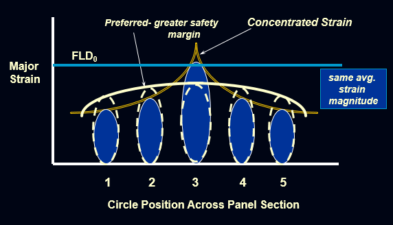
The mild steel currently being used for sheet metal stampings has higher n-values than High Strength Low Alloy Steel and Advanced High Strength Steel. The high n-value indicates that the material has a higher work hardening exponent making the steel much easier to stretch or form. The n-value describes how the material works together to resist localized fractures as stresses are applied. High strain patterns can be created in localized areas such as character lines and embossments. This strain pattern creates strain peaks or strain gradients. These strain peaks have much higher plastic deformation than areas on the rest of the material. The localized strain will cause the material to thin as it forms the character line or embossment. The die geometry does not allow the material to deform in stretch or draw modes, which means the material is in the plane strain mode of deformation on the Forming Limit Diagram (FLD). This deformation mode has the least amount of formability due to the location of the FLD₀anchoring point (See Figure 1).
Figure 1: Benefits of Uniformed Strain Distribution.
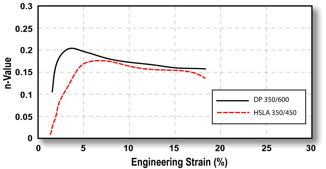
What does that mean for your stamping process? Mild steel has the ability to reach a high strain gradient due to higher n-values. High strength steels do not have the ability to reach the higher peak gradients due to lower n-values and less stretchability. These high strain areas will be more susceptible to a greater amount of thinning and/or fractures. If changes in the stamping process occur, such as reduced lube quantity, greater thinning can occur, at times exceeding minimum thickness and resulting in metal fracture. These concerns can be minimized through a better understanding of material capabilities, specific geometry effects, and the use of process recipe discipline. For example, Figure 2 compares the instantaneous n-value for Dual Phase steel, a member of the AHSS family, to HSLA steel. The early n-value increase reflects enhanced local formability, which is observed in stamped parts, contrary to what the typical stress-strain curve does not show the early n-value increase, which reflects enhanced formability in local regions of stamped parts. Other AHSS grades don’t show this tendency but have been developed with greater concentrations of bainite or finer dispersion of martensite within a ferrite matrix; both effects result in better localized forming.
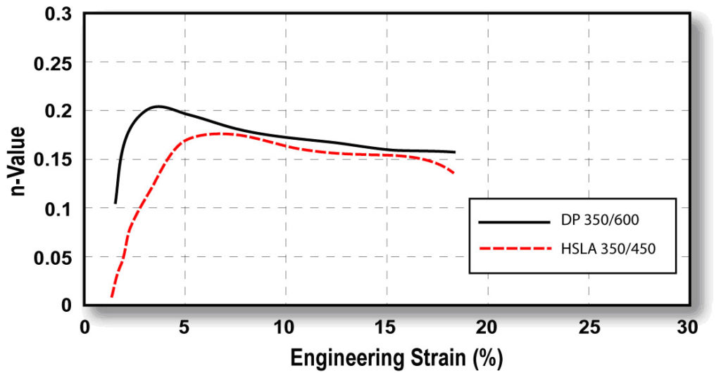
Figure 2: Instantaneous n-values versus strain for DP 350/600 and HSLA 350/450 steels.
Training die makers to understand these effects, while managing die geometry, will have a dramatic effect on the rework, downtime, and scrap associated with a conversion to AHSS products. The use of FLD₀ and formability analysis should identify areas of concern on the stamped part, but should also be coupled with hole expansion testing, or 2-D tension tests to more fully explore the formability condition. When trouble areas have been identified, there should be a review of the analysis and part with T&D managers, die makers, and quality personnel to formulate a corrective action plan. This plan should have specific and measurable direction, buy in, and understanding of the impact that die changes will have to the existing process.
BONUS!
Watch a video of renowned metallurgist Dr. Stuart Keeler explaining AHSS Instantaneous n-value:
Keeler On N-Value from worldautosteel on Vimeo.
Contributions made by Phoenix Group.
Figure 2 Image provided courtesy of Dr. Stuart Keeler.
News
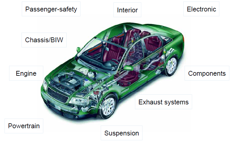
Figure 1: Laser Welding is commonly found in these vehicle subsystems.
Laser welding is finding its way into more vehicle applications due to inherent weld strength, adaptability to complex weld geometries, and lower part distortion (Figure 1). Automotive applications use a variety of welding joint designs for laser welding in both lap joint and seam butt joint configurations as shown in Figure 2. For example, laser butt-welding is used for welding tubes in roll-forming production lines as an alternative method for high frequency induction welding. Seam welds on butt joints need less power from the machine than lap joints due to the smaller weld fusion area, producing less distortion and a smaller heat affected zone (HAZ). Butt joint configurations are more cost efficient, however, the fit up for seam welds can be more difficult to obtain than those of lap joints.
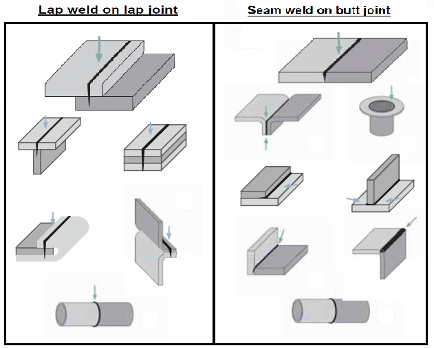
Figure 2: Common seam and joint types for laser welding of automotive applications.
When seam welding butt joint configurations, a general guideline for fit-up requirements include a gap of 3-10% the thickness of the thinnest sheet being welded, and an offset of 5-12% thickness of the thinnest sheet. Conversely, lap joints can require a gap of 5-10% the thickness of the top sheet being welded (Figure 3).
Laser welding is often used for AHSS lap (overlap) joints, but of course use different parameters compared to seam butt joint configurations. This type of weld is either a conventional weld with approximately 50% penetration in the bottom sheet or an edge weld. Welding is performed in the same way as for mild steels, but the clamping forces needed for a good joint fit-up are higher with AHSS than for mild steels. Lap joints tend to provide a larger process window, which can compensate for some of the manufacturing difficulties with AHSS, including springback and part distortion.
To achieve good laser-welded overlap joints for Zn-coated AHSS, a small intermittent gap (0.1-0.2 mm) between the sheets is recommended, which is identical to Zn-coated mild steels. In this way, the Zn does not get trapped in the melt, avoiding pores and other imperfections. An excessive gap can create an undesirable underfill on the topside of the weld.
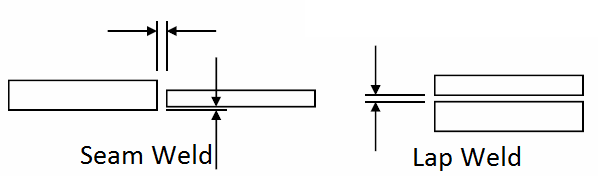
Figure 3: Fit-up requirements for butt joint and lap joint configurations in laser welding.
Studies have shown laser welding Zn-coated steels can be done without using a gap between the overlapped sheets. This is accomplished using dual laser beams. While the first beam is used to heat and evaporate the Zn coating, the second beam performs the welding. The dual laser beam configuration combines two laser-focusing heads using custom-designed fixtures.
AHSS grades can be laser butt-welded and are used in production of tailored products (tailor-welded blanks and tubes). The requirements for edge preparation of AHSS are similar to mild steels – in both cases, a good quality edge and a good fit-up are critical to achieve good quality welds.
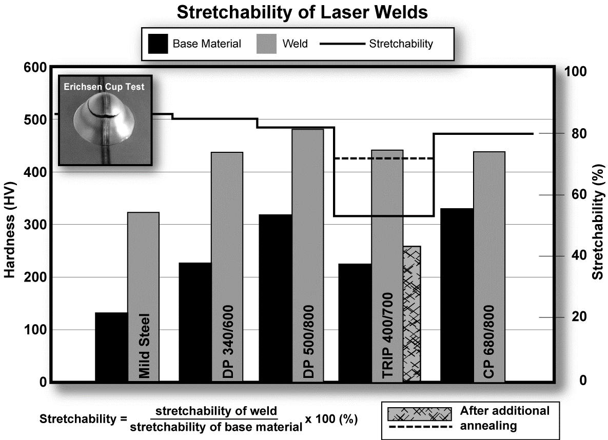
If a tailor-welded product is intended for use in a forming operation, a general stretchability test such as the Erichsen Olsen cup test can be used for assessment of the formability of the laser weld. AHSS with tensile strengths up to 800 MPa show good Erichsen test values (Figure 4).
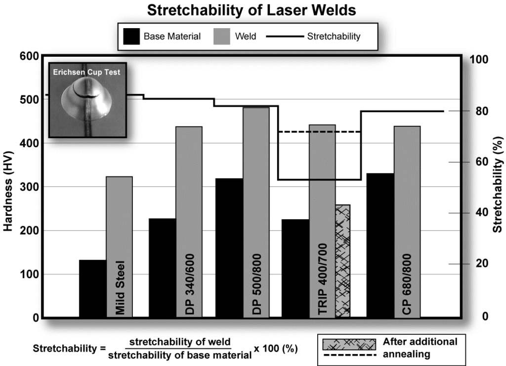
Figure 4: Hardness and stretchability of laser butt welds with two AHSS sheets of the same thickness (Erichsen test values describe the stretchability.)
The hardness of the laser welds for AHSS is higher than for mild steels (Figure 5). However, good stretchability ratios in the Erichsen test can still be achieved when the difference in hardness between weld metal and base metal is only slightly higher for AHSS compared to mild steels. If the hardness of the weld is too high, a post-annealing treatment (using HF-equipment or a second laser scan) may be used to reduce the hardness and improve the stretchability of the weld.
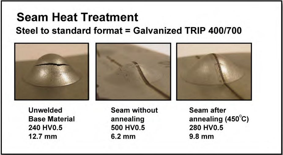
Figure 5: Improved stretchability of AHSS laser welds with an induction heating post-Heat treatment (Testing performed with Erichsen cup test)
Contributed by Menachem Kimchi, Ohio State University
Imagery and work thus represented is provided as follows:
Figure 2 and 3: Courtesy of TRUMPF
Figure 4: H. Beenken, “Joining of AHSS versus Mild Steel,” Processing State-of-the-Art Multi-phase Steel; European Automotive Supplier Conference, Berlin (September 23, 2004).
Figure 5: Courtesy of ThyssenKrupp Stahl.
News
Arc welds are normally used for vehicle components where the loads are high, for example in shock towers and engine cradles. Conventional arc welding processes (GMAW, TIG, and plasma) can be used as effectively for AHSS as with mild steels. The same shielding gases can be used for both, and arc weld strength can often be equivalent to the base metal with shorter welds (although increasing the length of the weld usually achieves greater weld strength). By adjusting the number and length (that is the total joined area) of welds, the fatigue strength of the joint can be improved. Fatigue strength of arc welds is generally superior to spot welds.
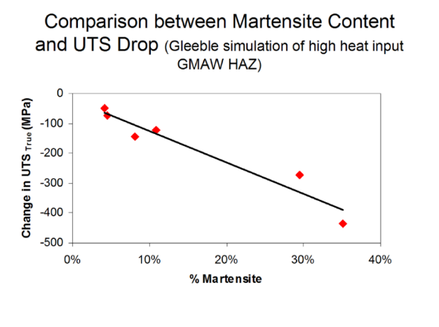
Figure 1: Martensite content compared to tensile strength.
Despite the increased alloying content used for AHSS, there are no increased arc welding imperfections compared with mild steel. The strength of the welds for AHSS increases with increasing base metal strength and sometimes with decreasing heat input. Depending on the chemical composition of AHSS [for example, mild Steels and DP steels with high martensite content and strength levels more than 800 MPa], the strength of the weld joint may be reduced in comparison to the base metal strength due to small soft zones in HAZ (Figure 1). For CP and TRIP grades, no soft zones occur in HAZ due to the higher alloying content for these steels in comparison to DP and mild steels.
Higher strength filler wires are recommended for welding of AHSS grades with strength levels higher than 800 MPa. It should be noted that higher strength fillers are more expensive and, more importantly, less tolerant to the presence of any weld imperfections. When welding AHSS to lower strength or mild steel, it is recommended that filler wire with 70 ksi (483 MPa) strength be used. Single-sided welded lap joints are normally used in the automotive industry, but due to the unsymmetrical loading and the extra bending moment associated with this type of joint, the strength of this lap joint is lower than that of the butt joint.
Gap Control
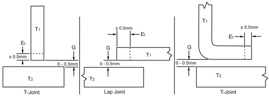
Figure 2: Joint design tolerance.
For automotive applications, a design gap tolerance (G) of 0-0.5 mm is allowed for all weld joints, as illustrated in Figure 2. An edge trim tolerance (Et) of ±0.5 mm is required where the edge is part of the weld joint, shown in this same figure.
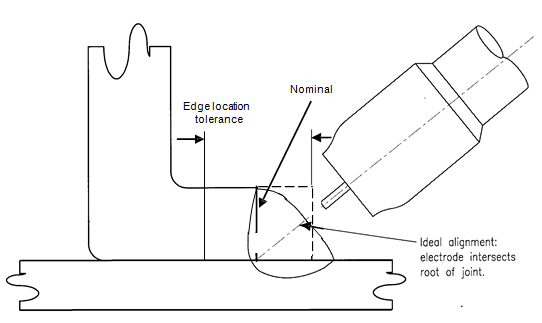
Figure 3: Edge location tolerance for fillet weld in a lap joint.
The variation in edge location causes variation in alignment of the electrode wire with the weld joint, as shown in Figure 3. Misalignment of the electrode may cause poor weld shape, improper fusion and burn-though. To control this variable, the trim tolerance at the weld joint must be held to ±0.5 mm and the electrode must maintain a root joint alignment tolerance of ±0.5 mm.

Figure 4: Maximum GMAW welding gap.
A tolerance stack-up review must be performed on all GMAW joints. The worst-case maximum designed gap including tolerance stack-up shall not exceed what is listed in Figure 4. It is preferable to target the smallest possible gap (the thickness of the thinnest sheet or 1.5 mm, whichever is smaller).
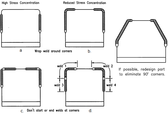
Figure 5: Reducing weld stress concentrations.
High-stress areas defined by CAE analysis and/or functional testing should be reviewed for weld optimization. Figure 5 illustrates techniques used to reduce the fillet weld stress concentration, which results in improved weld performance. These techniques include placing the weld start/stop away from corners and other high-stress areas, avoiding abrupt weld line direction changes when possible, etc.
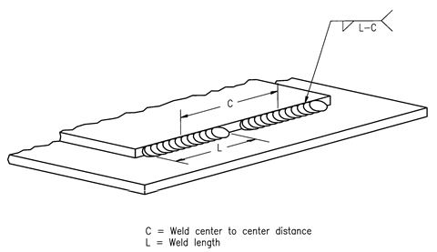
Figure 6: Intermittent fillet weld spacing.
Intermittent Welds – Intermittent welds can be employed as a method to reduce heat input and distortion (maintaining gap control), but they also introduce weld starts and weld stops, both of which are stress risers. Weld start/stops of intermittent welds should be placed away from high stress areas. Intermittent welds are specified by the center-to-center distance (i.e., pitch) and weld length, as shown in Figure 6.
Contributed by Menachem Kimchi, Ohio State University
Imagery and work thus represented is provided courtesy of Auto/Steel Partnership and AET Integration.
News
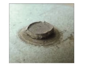
Figure 1: Full Button Nugget
Contributed by Menachem Kimchi, Ohio State University
Advance High-Strength Steels (AHSS) have been resistance welded in automotive production lines in the last few years. However, the high strength and hardness can be expected to affect spot weld failure modes during the typical peel testing and chisel testing performed for weld quality evaluation.
A well-established industry standard associated with peel testing of conventional steels is that an acceptable test is one in which the peel test “pulls a nugget” or a “full button,” as shown in Figure 1.
However, with AHSS, full button pulls are less likely due to the high Carbon Equivalent that are likely to produce hard weld nuggets. This fact is compounded by the higher yield strengths of the material that will tend to produce greater stresses concentrating at the edge of the nugget during a peel or chisel tests. Therefore, the conventional modes of testing such as peel and chisel testing may be more likely to produce interfacial or partial interfacial failure modes such as those shown in Figure 2.
With AHSS, these types of failure modes may occur even though the weld strengths may be acceptable for the intended application. Even full interfacial failures may exhibit high strength, although it may sometimes be challenging to differentiate between an interfacial failure and a “stuck” weld condition (which refers to an unfused bond of unacceptable strength).
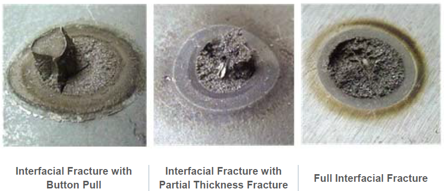
Figure 2: Failure Modes
To improve nugget failure modes with AHSS, the hard martensite must be softened. A simple and effective approach to accomplishing this is to add a temper cycle at the end of the weld (Figure 3), something that can easily be added at the end of the spot welding cycle. A sufficient amount of quench time must be included prior to tempering to allow the complete transformation to martensite, and the amount of tempering time and current will dictate how much softening occurs. Of course, the quench time adds cycle time to each weld, so production requirements mandate that this time be kept as short as possible. Depending on how hardenable the steel being welded is, other approaches that slow cooling rates may be helpful. These approaches include current pulsing, current sloping, longer weld times, and short hold times.
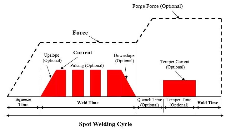
Figure 3: Spot Welding Cycle
News
The challenges to spot welding of aluminum compared to steel include a tenacious and rapidly forming oxide layer of variable thickness and composition, high electrical and thermal conductivities, small increases in resistivity with temperature, a narrow plastic range, low melting temperatures, and a high coefficient of thermal expansion. Used by permission from Menachem Kimchi,Assistant Professor-Clinical, Materials Science Engineering, Ohio State University, this excerpt from a new book by Kimchi and David Philips, Resistance Spot Welding Fundamentals and Applications for the Automotive Industry, explains these differences for those who wish a deeper understanding. This article is the first of a series by Kimchi on welding of Advanced High-Strength Steels, so stay tuned!
Thermal Conductivity and Electrical Resistivity
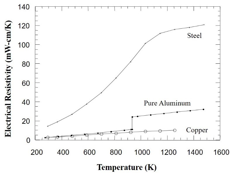
Figure 1: Electrical Resistivity of Steel and Aluminium
(compared to copper electrodes)
The Resistance Spot Welding process, one of the primary processes used in the automotive industry, works best with metal alloys such as steels that have electrical and thermal conductivities that are much lower than the copper-based electrodes used to weld them. Low electrical conductivity (or high resistivity) provides for easy I2R heating, and low thermal conductivity means heat will be extracted from the weld nugget region more slowly. The longer it takes for heat to extract, the more robust the weld. As shown in Figure 1, steel has a very high resistivity and therefore is ideal for this welding process.
Aluminum exhibits electrical and thermal conductivities that are close to copper, two additional reasons contributing to spot welding challenges with this metal. These properties dictate the need for much higher currents, and much shorter times, and therefore a less robust process. Rules of thumb regarding welding currents and times for aluminium is approximately three times the current temperature, and 1/3 of the process times for welding steel. Consequently, existing equipment cannot be used in welding aluminium because of the higher current required.
Plastic Range of Metal
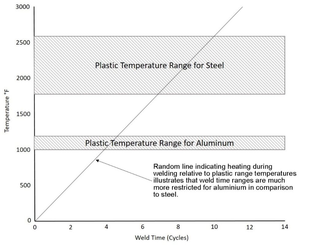
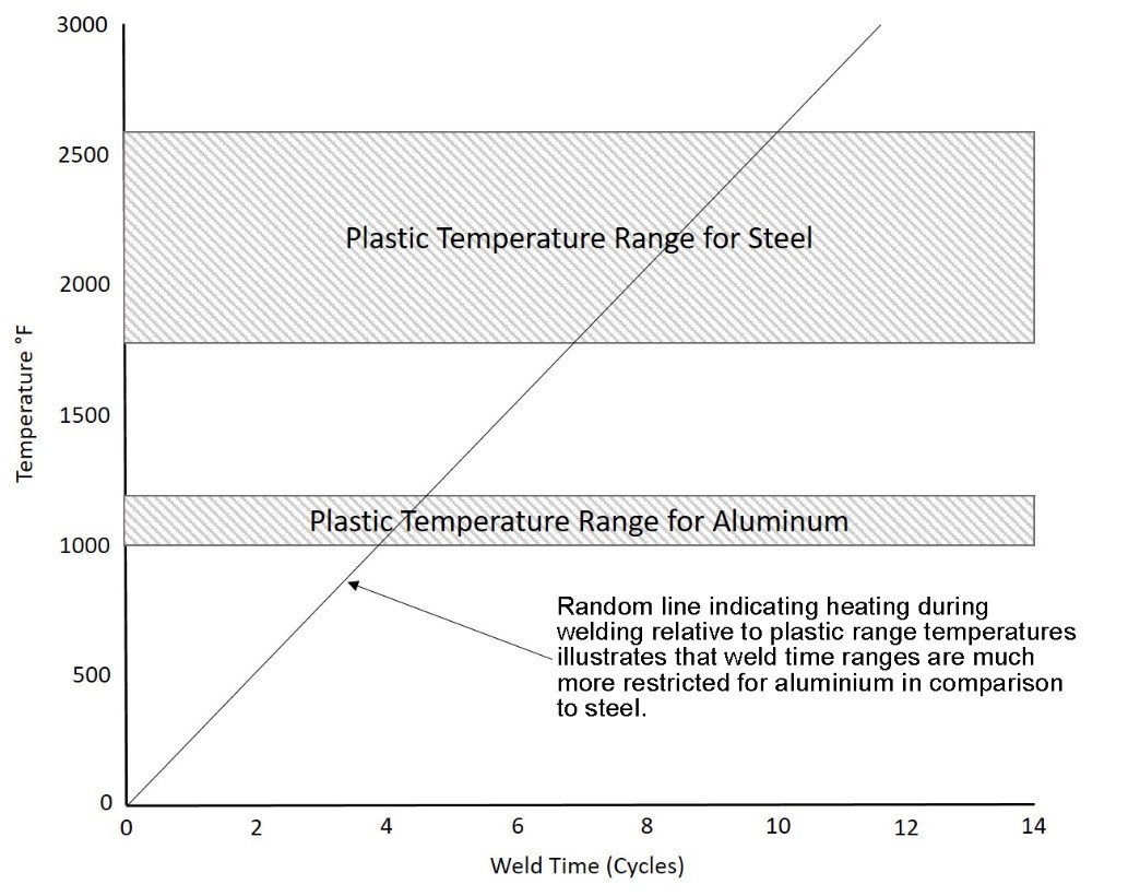
Figure 2: Typical Plastic Ranges, Steel vs. Aluminium
The plastic range of a metal can be loosely defined as the range of temperatures below its melting temperature in which the metal exhibits significant softening. The significance to spot welding is that wider plastic ranges will create a wider softened region around the weld for a longer time. This region, in conjunction with the electrode pressure, effectively “seals” the rapidly expanding (metals exhibit large volumetric expansions when they melt) molten weld nugget, and prevents it from being ejected from the weld zone (expulsion). As indicated on Figure 2 the typical plastic range of aluminum is significantly less than that of steel. The figure also includes a random heating line to illustrate the fact that a narrow plastic range not only reduces the width of the “seal” around the nugget, but also suggests that the window of welding time to produce a good weld is restricted. In summary, the narrow plastic range of aluminum combined with its low melting temperature means that the process window to create a good weld and avoid expulsion is very small.
Dynamic Resistance
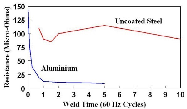
Figure 3: Dynamic Resistance Curve for
Steel Vs. Aluminium
As indicated on Figure 3, the dynamic resistance curve for aluminum is entirely different from the curve for steel. Two facts contribute to this vast difference:
1) The oxide on the surface of the aluminum, and
2) The small change in resistivity as a function of temperature.
Upon initial flow of current, resistances are extremely high due to the oxide layer which has much higher resistivity than the aluminium. This increases the likelihood of initial expulsion and will also result in significant electrode heating. The oxide layer quickly breaks down allowing current to pass more easily as resistance drops rapidly. However, as compared to the dynamic resistance curve for steel, there is no significant increase in resistance later in the cycle. The reason for this is compared to steel, aluminum’s resistivity increases only slightly with temperature as shown in Figure 3. The implication of this difference is that there is limited opportunity to grow the nugget by taking advantage of the rapid increase in resistivity, as is the case with steel.
Coefficient of Thermal Expansion
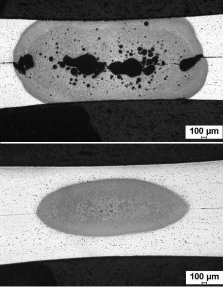
Figure 4: Aluminium Weld Discontinuities (Porosity)
Aluminum’s thermal expansion coefficient is roughly three times higher than steel. This results in greater volumetric expansion of the metal upon heating, and subsequent greater contraction upon cooling. The consequence is a greater chance not only for expulsion, but weld discontinuities such as porosity and solidification cracking (Figure 4). This may mandate the need for low inertia, fast “follow-up” weld heads which can maintain consistent force during the rapid movement of the expanding and contracting weld region. This requires more equipment and expense for the process.
Aluminium’s Oxide Layer
As discussed previously, aluminum forms an oxide layer that is tenacious and forms rapidly. The highly resistive oxide layer can be a benefit in that it significantly increases contact resistance between the sheets being welded. But maintaining a consistent oxide layer thickness is difficult since it happens naturally and rapidly as it is exposed to the environment. Because it is inconsistent, it causes inconsistencies in the weld.
On the other hand, if the oxide layer is significantly reduced by mechanical (such as grinding) or chemical (such as acid cleaning followed by a conversion treatment) methods immediately prior to welding, the need for extremely high currents will be mandated which will promote electrode sticking and accelerated wear.
News
With escalating concerns about human-induced greenhouse gases, global legislators have passed more stringent vehicle emissions regulations through 2020, while considering further, aggressive targets for the next ten years. Automakers are searching for new materials and engineering capabilities to meet requirements that often conflict. As an example, structural applications require materials characterized by high strength and stiffness, often achieved with greater thickness. But fuel economy and emissions are positively impacted when component thickness is reduced. New vehicle designs with complex geometries are aesthetically pleasing, but difficult to form and join, compromised further by thickness reduction to achieve mass reduction targets. The global steel industry continues to develop new grades of steel, defined by ever-increasing strength and formability capabilities, continually reinventing this diverse material to address these opposing demands. These Advanced High-Strength Steels (AHSS) are characterized by unique microstructures and metallurgical properties that allow OEM’s to meet the diverse functional requirements of today’s vehicles.
AHSS are complex, sophisticated materials, with carefully selected chemical compositions and multiphase microstructures resulting from precisely controlled heating and cooling processes. Various strengthening mechanisms are employed to achieve a range of strength, ductility, toughness, and fatigue properties.
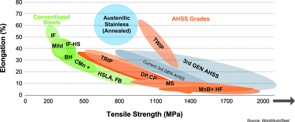
The AHSS family includes Dual Phase (DP), Complex-Phase (CP), Ferritic-Bainitic (FB), Martensitic (MS or MART), Transformation-Induced Plasticity (TRIP), Hot-Formed (HF), and Twinning-Induced Plasticity (TWIP). These 1st and 2nd Generation AHSS grades are uniquely qualified to meet the functional performance demands of certain parts. For example, DP and TRIP steels are excellent in the crash zones of the car for their high energy absorption. For structural elements of the passenger compartment, extremely high-strength steels, such as Martensitic and boron-based Press Hardened Steels (PHS) result in improved safety performance. Recently there has been increased funding and research for the development of the “3rd Generation” of AHSS. These are steels with special alloying and thermo-mechanical processing to achieve improved strength-ductility combinations compared to present grades, with potential for more efficient joining capabilities, at lower costs. The broad range of properties is best illustrated by the famous Steel Strength Ductility Diagram, captured in the figure.
Steel Strength Ductility Diagram
AHSS grades contain significant alloying and two or more phases. The multiple phases provide increased strength and ductility not attainable with single phase steels, such as high strength, low alloy (HSLA) grades. HSLA materials achieve their strength through alloying and solid solution hardening, whereas AHSS are produced by using specific alloys and precise thermomechanical processing.
In the past, steels with tensile strength (UTS) levels in excess of 550 MPa were generally categorized as AHSS, and the name “ultra high-strength steels” was reserved for tensile strengths exceeding 780 MPa. However, today there are multiple phase AHSS with tensile strengths as low as 440 MPa, and so using strength as the threshold for whether a steel qualifies as “AHSS” is no longer suitable. AHSS with tensile strengths of at least 1000 MPa are often called “GigaPascal steel” (1000 MPa = 1GPa). Third Generation AHSS seeks to offer comparable or improved capabilities at significantly lower cost.
Contributions made by Phoenix Group.