The WorldAutoSteel Steel E-Motive program has been moving along now for nearly a year, and we’d like to share an update with you, our engineering colleagues, on some of the design decisions we’re facing. If you recall, the Steel E-Motive program is designing vehicle concepts for Mobility as a Service (MaaS), characterized by autonomous, electric, ride sharing vehicles.
Some Background
We partnered with Ricardo headquartered in the UK to conduct the design and engineering of the vehicles. Ricardo was selected for their well-known reputation for innovation, their demonstrated knowledge of vehicle powertrains and electrification and their commitment to sustainable transportation. Our steel members subject matter experts work with Ricardo via various teams and working groups to push the envelope of steel applications. And given our pandemic, all of this currently occurs via virtual meetings.
Targeting technologies available for deployment in 2030+, we are considering the impacts to vehicle manufacturers, fleet operators and the ride hailing customer, as MaaS inevitably leads to an increase in demand for vehicle sharing, rental models and ride-hailing services over the next decade. We can represent these requirements as shown in Figure 1. On the left you’ll see broad needs for the critical stakeholders including space efficiency, flexibility and total cost of ownership. Those requirements translate into 12 key considerations for the mobility service provider, shown on the right, aimed at delivering value to customers and a sustainable and profitable business model. These considerations then require innovative design, engineering and materials applications.
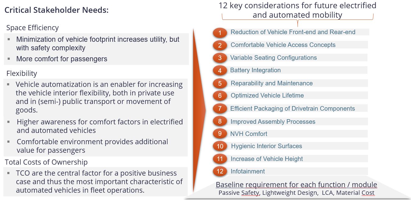
Figure 1: MaaS key attributes and functions.
There are four main phases to Steel E-Motive (Figure 2). Phase 0 was a 3-month pre-study, beginning 30 June 2020, to review and confirm vehicle targets, essentially defining the foundations, goals and approach for the project. On 1 October 2020, we entered the Phase 1 concept engineering, exploring the challenges and steel solutions for Level 5 autonomous vehicles. Essentially, we are designing the body structure in this Phase, utilizing CAE tools to guide us. Phase 2 focusses on further refinement and optimization of the selected body concept, and ensuring the design is fully validated as there will be no working prototypes or hardware produced in the project. Phase 3 will be the roll out and dissemination activities, although you will see from the Steel E-Motive website and blogs that we are continually releasing material throughout the project.
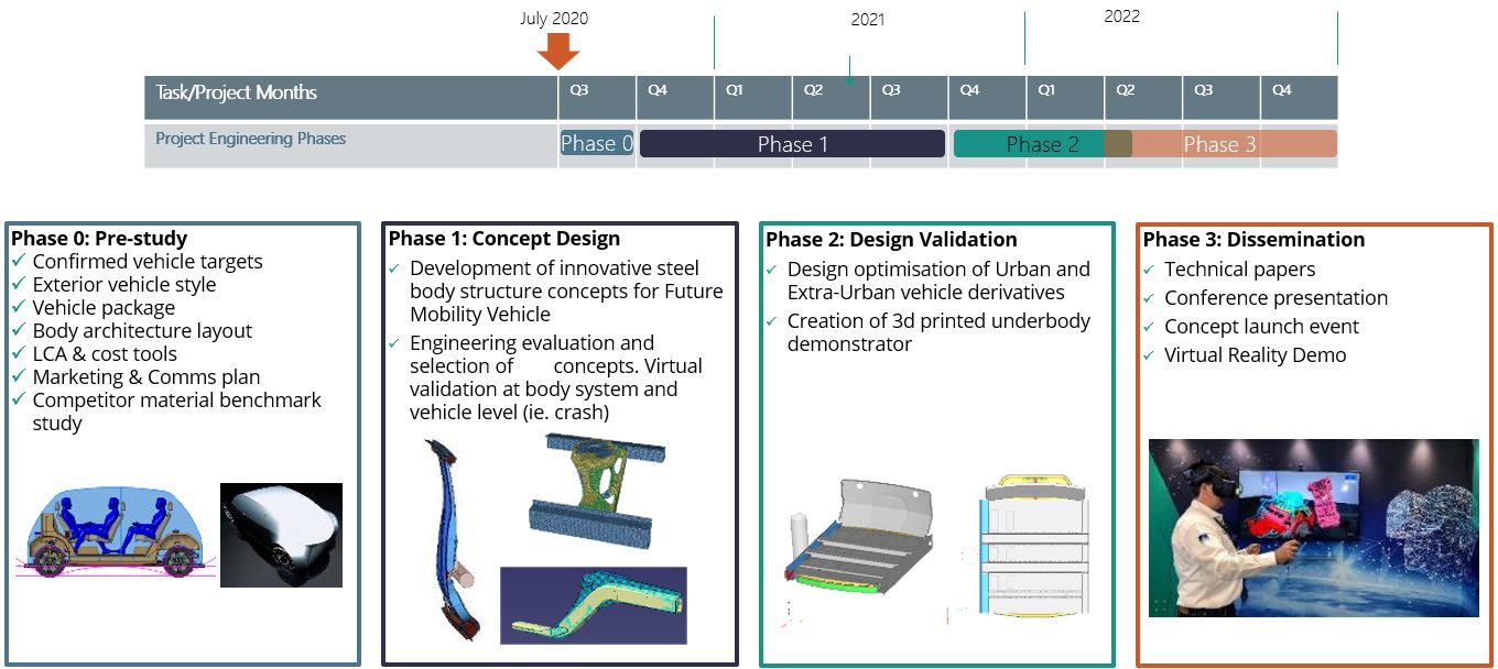
Figure 2: Project timing and key activities.
We’ll be disclosing detailed targets and specifications later in the program, but Figure 3 provides overall dimensions. Battery electric will be the primary propulsion with competitive range. There are two variants: urban for inner city and shorter journeys, and an extra-urban variant for longer city-to-city (or city-to-airport) journeys. With Level 5 autonomy, there are no direct driver interfaces such as the steering column and pedals. You can see from the Figure that the vehicles are fairly compact. The urban variant sits between a European B and C segment in size. The extra-urban vehicle has a stretched wheelbase and can accommodate up to six passengers and a greater luggage capacity.
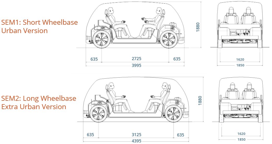
Figure 3: SEM vehicle technical specification and dimensions – base vehicle geometry.
The vehicles will be engineered and purposed for global application; therefore, we are considering the major global crash and safety standards and load cases. High volume production is targeted, greater than 250,000 units per annum, and a hypothetical production date of 2030, which influences the steel grades and fabrication processes considered. Third Generation AHSS (3rd Gen AHSS) and press-hardened steels continue to evolve with higher strength and improved formability. Between these innovative product capabilities, we are addressing the challenges associated with Mobility as a Service and tackling geometries that otherwise would have been difficult to produce.
To further assist in the design and manufacture of efficient vehicle structures, there are many new manufacturing processes, such as roll forming and hot stamping, that help fabricate these stronger materials effectively, while often doubling material use efficiency. Figure 4 provides a list of technologies that will be considered for Steel E-Motive.
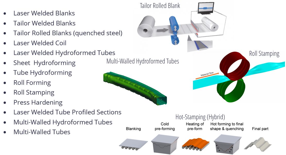
Figure 4: Steel technologies included in SEM’s portfolio.
With the portfolio of steel product and manufacturing processes already available and the addition of those forecasted for future commercial availability, we are expecting innovations that will be a roadmap for future mobility vehicle manufacturers.
Our end goal is to demonstrate multi-purpose opportunities for the vehicles via a modular architecture enabled by the application of innovative steel solutions. These solutions will help Steel E-Motive achieve a low environment footprint measured over the vehicle Life Cycle, and meet global crash standards while delivering the lowest Total Cost of Ownership (TCO).
To reach our goal of demonstrating steel innovation in this program, we are using a theoretical frameworkH-2 as a guide, shown in Figure 5, considering innovation at an architectural level. That is, using body structure load paths shown in the vertical axis, and modular innovation for the major body components such as battery enclosure, side/crash rails, shown in the horizontal axis. Combining innovation levels and types of the two axes should enable us to demonstrate radical innovation in Steel E-Motive.
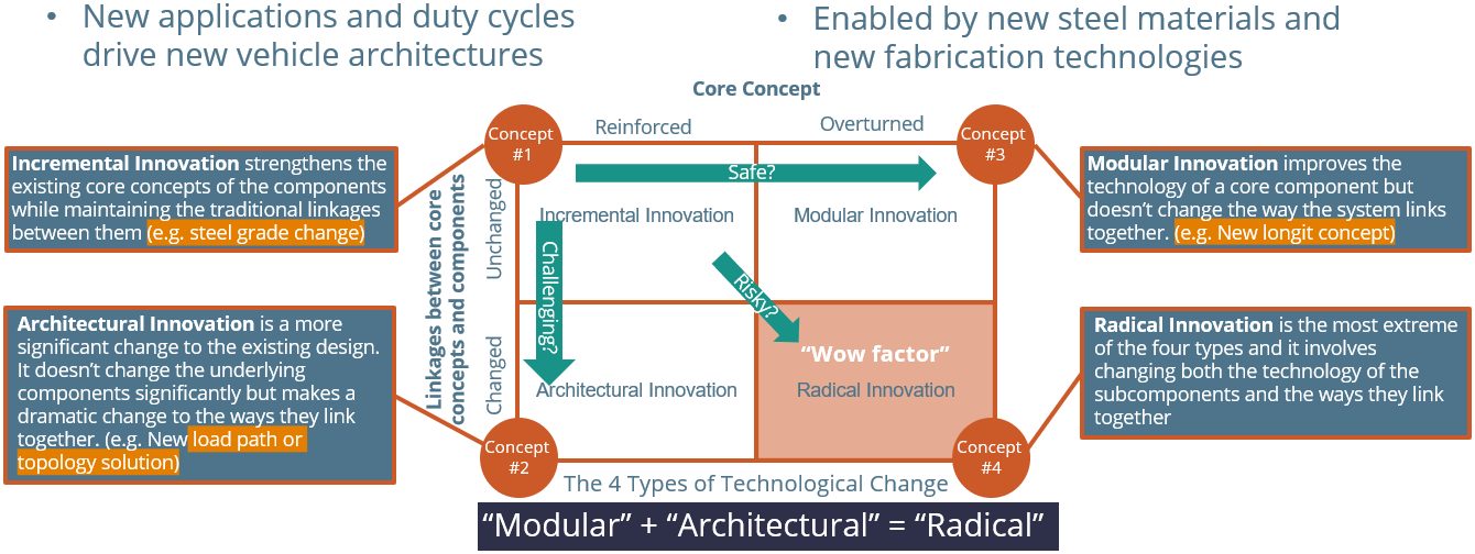
Figure 5: Steel E-Motive explores and demonstrates steel innovation. Exploring “modular” and “architectural” innovations for 2030 production.
Design Challenges
Figure 6 reveals an early or basic Steel E-Motive architecture. You can see that Level 5 autonomy creates both design freedoms that allow new occupant seating positions, while also creating challenges for short front and rear overhangs. We have an open pod-type structure with large door apertures for enhanced occupant ergonomics.
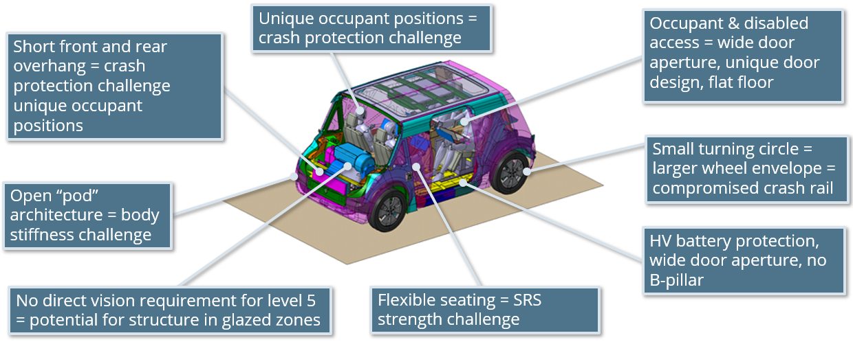
Figure 6: Challenges and opportunities of Level 5 autonomous MaaS battery electric vehicle.
Passenger comfort is key for MaaS vehicles. The open pod structure may give challenges with the air cavity mode coupling with structural modes. With occupants in different positions, we have different NVH source-path-receiver paths to consider. The larger door aperture gives us an inherent deficiency in overall body structure stiffness, for which we need to compensate. As with any BEV, the mass of the battery suspended on the lower structure may reduce body modes to frequencies that interact with other vehicle systems such as suspension modes. With a lot of emphasis on lower structure crash zones and battery protection, we may encounter some lower frequency upper body modes (such as lozenging), especially as we are targeting low overall body mass. These NVH risks and challenges are being addressed by taking a modal mapping approach, utilizing steel’s inherent high structural stiffness properties and undertaking thorough NVH simulation throughout the engineering phases.
Level 5 autonomy removes the requirements for driver vision and obscuration, but we do need to acknowledge passenger comfort issues, such as motion sickness. Consequently the designs consider a good level of outward visibility. However, we now have the freedom to place structure where we could not previously. We are using 3D topology FEA tools to help determine the optimum placement of structure in the body, and we have allowed the tool the freedom to place structure in the front and rear glazed areas. In the Figure 7 example, the software is recommending some structural members across the front windscreen, and further analysis shows that this has the potential to give us an overall Body-In-White weight saving as the load paths are more evenly distributed.
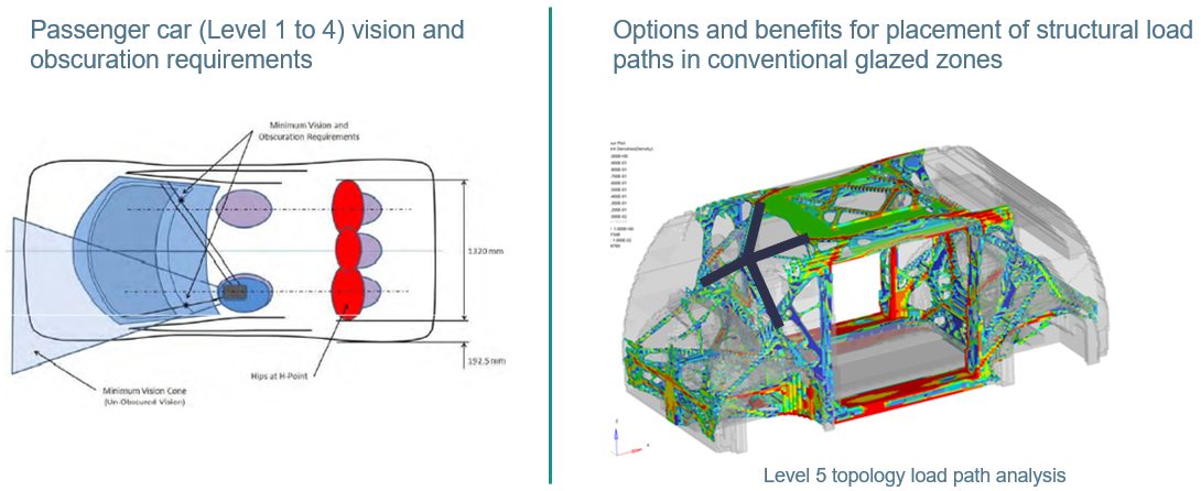
Figure 7: Level 5 autonomy removes the driver vision and obscuration requirements—an opportunity for new solutions.
To summarize the Steel E-Motive engineering activities, we are currently exploring the numerous challenges and opportunities that Level 5 autonomous BEVs provide us. We are in the concept phase, investigating both the overall body structure layout and load paths, as well as developing components and modules utilizing the unique properties of steel.
We expect to complete the program with full virtual concepts by December 2022. Our plans are to unveil more and more of the design concepts over the months to come, and we’ll be using virtual reality and other tools to communicate the concepts’ engineering. We invite you to subscribe at the website to receive all the news that will be coming out of the program, including more technical details as they become available. You can do that at www.steelemotive.world. We’re excited to share Steel E-Motive innovations in the future!